Introduction: The Evolving Landscape of Precision Manufacturing
The demand for rapid prototyping and the production of complex geometric components has surged across all major industrial sectors. Modern engineering teams face immense pressure to accelerate product development lifecycles while maintaining strict quality standards. This dynamic environment requires highly reliable manufacturing solutions that can seamlessly bridge the gap between digital design and physical validation.
Among these solutions, computer numerical control (CNC) machining remains a cornerstone of the modern manufacturing lifecycle. It offers unmatched repeatability, scalability, and material versatility compared to additive manufacturing alternatives. As product designs become increasingly intricate, the reliance on high-precision subtractive methods grows proportionally.
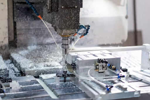
As modern product development cycles shrink, engineers increasingly rely on advanced manufacturing to transform digital 3D models into functional physical components. Whether dealing with intricate 5-axis geometries for aerospace applications or tight-tolerance brackets for automotive assemblies, sourcing professional cnc milling parts ensures rapid turnaround times without sacrificing dimensional accuracy.
By leveraging automated toolpaths and sophisticated multi-axis machinery, production facilities can now achieve surface finishes and dimensional accuracies that were previously unattainable. This technological leap allows design teams to iterate faster, test more rigorously, and ultimately bring superior hardware products to market with confidence.
Mastering Tolerances and Multi-Axis Milling Capabilities
Understanding machine capabilities is fundamental to optimizing part design and controlling manufacturing costs. Standard 3-axis CNC milling is highly efficient for planar geometries, where the cutting tool moves along the X, Y, and Z axes. However, this setup often requires multiple manual realignments when machining features on different faces of a part, which can introduce tolerance stacking errors.
To address complex side features and undercuts, manufacturers turn to 4-axis and 5-axis indexing or continuous milling. In a 5-axis setup, the cutting tool and the workpiece move simultaneously across five different axes. This capability drastically reduces the need for multiple setups, ensuring superior alignment of complex geometries and significantly lowering the risk of human error during repositioning.
Strict tolerance control is the lifeblood of critical industries such as aerospace, medical device manufacturing, and automotive engineering. Standard CNC machining tolerances typically hover around ±0.125 mm. However, high-performance applications often require tight tolerances reaching down to ±0.025 mm or even ±0.005 mm for specialized components like bearing housings or aerospace turbine blades.
Achieving these extreme micro-level tolerances demands not only advanced 5-axis machinery but also meticulous thermal control of the manufacturing environment. Engineers must specify critical tolerances only where absolutely necessary, as over-tolerancing non-critical dimensions can exponentially increase machining time, tool wear, and overall production costs.
Material Selection Strategy: Metals vs. Engineering Plastics
Selecting the right material is a balancing act between mechanical requirements, environmental operating conditions, and manufacturability. High-strength metals are traditionally favored for load-bearing and high-temperature applications.
- Aluminum 6061-T6: Known for excellent machinability, a high strength-to-weight ratio, and good corrosion resistance. It is the default choice for general-purpose structural components and aerospace fixtures.
- Stainless Steel (304/316L): Offers superior tensile strength and extreme corrosion resistance. While harder to machine than aluminum, it is essential for medical devices and fluid-handling systems.
- Titanium (Ti-6Al-4V): Provides exceptional strength, low weight, and biocompatibility. Its poor thermal conductivity makes it notoriously difficult to machine, requiring specialized tooling and slower feed rates.
Conversely, high-performance engineering plastics are increasingly replacing metals in applications requiring electrical insulation, chemical resistance, or weight reduction. These materials offer excellent machinability but require distinct cutting strategies to prevent heat buildup and warping.
- PEEK (Polyetheretherketone): An advanced thermoplastic that maintains high mechanical strength at extreme temperatures (up to 250°C). It is frequently used in aerospace and medical implants.
- POM (Delrin/Acetal): Features high stiffness, low friction, and excellent dimensional stability. It is ideal for precision gears, bearings, and snap-fit assemblies.
- Nylon: Highly durable and resistant to wear and abrasion. It is commonly utilized for custom jigs, fixtures, and low-friction sliding components.
When specifying materials, engineers must weigh the raw material cost against the machining time. For instance, while POM is cheaper and faster to machine than Titanium, it cannot survive high-heat environments. A thorough analysis of yield strength, thermal expansion coefficients, and friction properties is mandatory for optimal material selection.
Optimizing CAD Models and Design for Manufacturability (DFM)
Design for Manufacturability (DFM) is the proactive practice of designing parts so they are easy and cost-effective to produce. A poorly optimized CAD model can lead to excessive tool changes, chatter, and wasted material. The first rule of DFM in CNC milling is to minimize the depth of internal cavities.
Deep pockets require long, slender end mills that are prone to deflection and vibration. As a best practice, cavity depths should not exceed four times the tool diameter. If deeper pockets are unavoidable, engineers should consider incorporating a variable wall thickness or designing the component as an assembly of simpler, shallower parts.
- Internal Radii: Sharp internal corners cannot be machined by rotating cylindrical tools. Always specify internal corner radii that are slightly larger than the cutting tool’s radius to prevent the tool from stopping in the corner.
- Standardize Features: Use standard sizes for holes, threads, and counterbores to eliminate the need for custom cutting tools, thereby reducing setup times and tooling costs.
- Limit Setups: Design parts so that most, if not all, features can be machined from a single direction. Every time a part is flipped or rotated, labor costs increase and precision decreases.
By integrating these DFM principles early in the CAD modeling phase, engineering teams can drastically reduce manufacturing bottlenecks. Front-end design optimization directly influences the efficiency of the toolpath generation, ultimately leading to faster production cycles and improved cost-efficiency for the final product.
Key Takeaways
| Area | Key Takeaway | Impact/Data |
| Precision | Limit tight tolerances strictly to critical features | Standard: ±0.125 mm; High-precision: ±0.005 mm |
| Multi-Axis | Adopt 5-axis continuous milling | Eliminates repositioning setups and tolerance stackup |
| DFM | Cap internal cavity depth strictly | Max 4x tool diameter; prevents tool deflection/chatter |
| Materials | Match material properties to operating thermal stress | PEEK operates ≤250°C; Ti requires reduced feed rates |
| Procurement | Leverage AI digital manufacturing platforms | Cuts NPI lead times from weeks to days |
Conclusion: Accelerating Time-to-Market Through Digital Manufacturing
The manufacturing sector is undergoing a profound transformation driven by digital integration and automation. Traditional quoting and procurement processes, which once took weeks, are being replaced by dynamic digital manufacturing platforms. These systems utilize AI-driven algorithms to instantly analyze CAD geometry, identify DFM issues, and generate accurate real-time pricing.
This digital approach empowers engineering teams to transition from rapid prototyping to low-volume production with unprecedented speed. By centralizing the supply chain and automating the design-check protocols through secure teamspaces, manufacturers can drastically reduce New Product Introduction (NPI) lead times and mitigate the risks associated with hardware development.
Looking ahead, the integration of automation, AI-driven prototyping, and digital platforms is redefining supply chain resilience. According to ongoing coverage by IndustryWeek, modern manufacturers are continuously adopting smart factory frameworks to optimize lead times and scale production efficiently across global markets.
Ultimately, mastering the nuances of CNC milling—from strict tolerance management and intelligent material selection to rigorous DFM practices—is essential for modern engineers. By combining deep technical knowledge with the agility of digital manufacturing networks, companies can build robust, scalable, and highly efficient production strategies.
